Borders - General and Grid Numbers
This settings page lets you define the drawing placement of the Border file, Key Plan and North Mark for the 2D output drawings.
Accessed from when you select the Borders > General and Grid Numbers node in the Settings interface.
You may have your own border files according to your company standard or project standard. You can customize the border drawing by copying your existing border file. The loading of border file allows you to load it after coping it to the ...\Border directory of the project folder when you setup the Orthographics Manager project.
The settings defined for the Border file are saved to a separate setting file named for the defined Border file. For example, the setting file for the E_Bord.dgn file defined below would be E_Bord.set. This file will be created in the same directory as the border file.
The next time you load the border file, the setting file will be loaded with the customized border drawing in the CAD Module.
Define the properties per the fields described below and Save the changes.
The Close icon closes the Project Settings interface, so make sure your changes are saved. You will be prompted to save them it you haven't already.
The Load Defaults icon in the main Settings interface will return the settings of the options page to their original values.
| Setting | Description |
|---|---|
| General Settings |
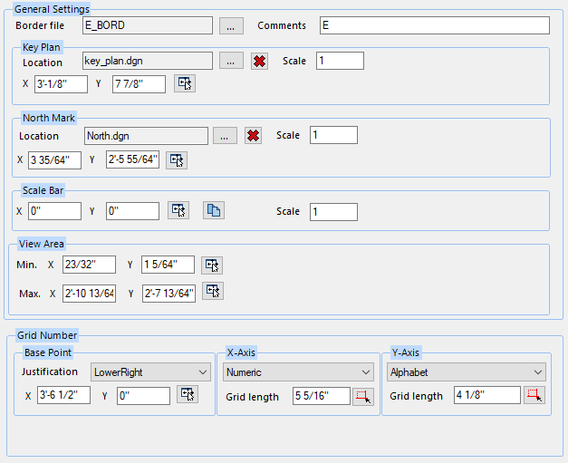
Border File: To load a Border File and its settings, click the Browse button next to the field to display a file selection dialog. The border files are generally stored in the %Project%\Border directory. If you have your own existing border files, you can copy them into this directory to be available to load and customize in the Orthographics Manager application. Comments: Enter desired comments into the field. |
| Key Plan |
This section lets you select a predefined Key plan to place on the drawing as well is location and scale using the fields below: File: To select which Key-plan to load, click the Browse button use the file selection dialog locate the file. The default location for the key-plan dgn files are in the %Project%\Border\Block directory. If you have existing Key-plan files, you can copy them into this directory. Note: A default
key-plan.dgn file is included with the sample projects available with the
Orthographics Manager install.
Coordinates: The X-Y coordinates define the lower left placement location for the key plan. Enter the coordinates directly into the fields. You can also pick the point directly in the CAD
Module. First you must click the View Border
Scale: If you want to apply a scale factor, enter a value onto the Scale field. The default scale value is 1. |
| North Mark |
Coordinates: The X-Y coordinates define the lower left placement location for the Scale Bar. Enter the coordinates directly into the fields. You can also pick the point directly in the CAD
Module. First you must click the View Border
Scale: After entering a scale factor into the
field, you can select the drawing file which matches the scale value by
clicking the icon
For example, if you want to add a 1/20 scale bar,
input 20 into the Scale field then click
Orthographics Manager will copy this file to the project Border\Scale Bar directory and name it 20.dgn. Whenever the view scale is set to 1/20, this file will be referenced. |
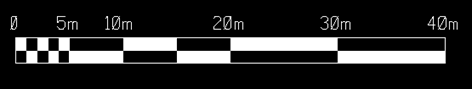
| Scale Bar | This section defines the position of the scale bar in
the final output drawing. The scale bar which displays is determined by the
Scale Factor set in the View Definition tab. The scale bar will look similiar
to the image below in the drawing:
The (X,Y) coordinates determines the location of
the scale bar in the drawing.
The scale bar images are stored in individual scale drawings (such as 36.dgn for a 1/36 scale). Click the
Select ScaleBar Reference
|
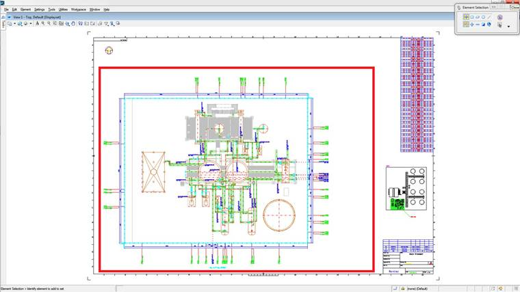
| View Area | The view area defines the region within the border
or frame where you can add the defined views. This does not include the area
for tables, key hatch, audit table etc.
Un the example below the red area defines the view area of the border. |
| Grid Number |
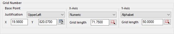
The fields in the Grid Number section define the settings for the grid in the drawing. Coordinates: The X-Y coordinates define the lower left placement location for the Grid Number. Enter the coordinates directly into the fields. You can also pick the point directly in the CAD
Module. First you must click the View Border
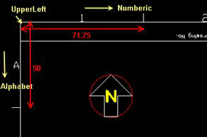
X-Axis: Determine the type of text to use ( Numeric, Alphabetic) for the X-Axis. Enter the Grid Length value into the field, or click the icon to the right and use to determine the grid length in the CAD Module. (Note that CAD Module must be open to do this.) Y-Axis: Determine the type of text to use ( Numeric, Alphabetic) for the X-Axis. Enter the Grid Length value into the field, or click the icon to the right and use to determine the grid length in the CAD Module. (Note that CAD Module must be open to do this.) The grid will be used for the Nozzle Chart. For the grid number to display you must check the Show Grid Number option in the Nozzle Charts page. The example below illustrates how the Grid Numbers are defined and displayed in the drawing. |
 icon to launch the application
then load the border file into the CAD Module. Click the
icon to launch the application
then load the border file into the CAD Module. Click the
 icon and use the mouse to pick
the location for the Key-plan. Left click the mouse to accept the location. The
coordinates of the placement point will be displayed in the X-Y fields.
icon and use the mouse to pick
the location for the Key-plan. Left click the mouse to accept the location. The
coordinates of the placement point will be displayed in the X-Y fields.
 next to the Scale field. This
opens a file selection dialog to the default Scale bar directory from which you
can select a scaled drawing.
next to the Scale field. This
opens a file selection dialog to the default Scale bar directory from which you
can select a scaled drawing.
 icon to browse to and select the
scale bar drawing to reference.
icon to browse to and select the
scale bar drawing to reference.